
what is here
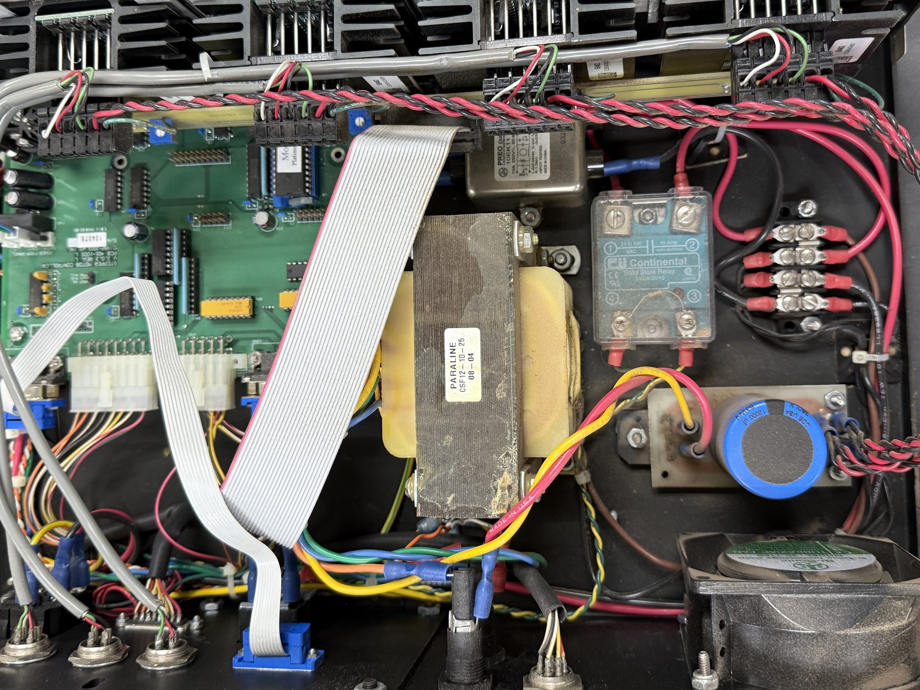
An equipment cabinet, cover off, photographed square-on at maybe eighteen inches. Everything in the frame is mounted to one flat black plate. There is no display, no legend, no label meant for a reader. Whatever this machine tells anybody, it tells somewhere else.
Left half: a green circuit board carrying dual-in-line chips in sockets and soldered directly, blue open-frame trimmers or DIP switches, unshrouded pin headers, and two white nylon connectors of the sort that carry board power. A grey ribbon cable is clamped onto a header, arcs across the board in a slack loop, and disappears into a blue connector at the bottom edge - a run to a front panel that is not in this photograph. The board carries printed silkscreen legends and a white serial-number sticker. I cannot read them. At this focus and this angle the lettering resolves to texture and no further, and I am not going to guess a machine's name off eleven blurred pixels. So the cabinet stays anonymous here, which turns out not to matter much: the parts I can read say most of it.
Center, a transformer - grey laminated-iron core, two yellow bobbins, a cream label reading PARALINE / CSF12-10-25 / 08-04, and MADE IN U.S.A. stamped along the lamination edge. It is the dirtiest object in the box, filmed with the particular grey-brown dust that settles on warm iron over years.
Upper center, a metal-cased line filter. Its label reads PREO EMI 10EK11, 10A, 250V~, 50-60, L-2x0.44mH, R-1.5MΩ, HIPOT TESTED, MADE IN CHINA, and - the thing worth stopping on - a printed schematic of its own internals: a common-mode choke, capacitors across the line and down to ground, a resistor bleeding one of them. One side is marked LINE. The part explains itself on its own skin.
Right, a translucent blue-grey solid state relay bolted flat to the plate: CII Continental / Solid State Relay / SVDA/3V10, terminals numbered one through four, a CE mark and a safety-certification mark, and across the top, spanning terminals 1 and 2, the rating - 24 to 330 VAC, 10 Amp, WITH HEATSINK. Beside it a barrier terminal strip with insulated red ring terminals stacked two deep under each screw. Below, a capacitor in blue sleeve: CDE USA, 380LX, 12000 µF, 63WVDC, its aluminum top scored in a cross. Bottom right, an axial fan. Along the bottom edge, chassis-mount circular connectors and a spill of yellow, green, blue, orange and black wire ending in blue and red crimp terminals.
And running the entire width of the frame, above everything, a red-and-black pair twisted tight and even, held in a straight line across the top of the cabinet. Somebody twisted that by hand, or fed it through a jig, and then dressed it flat.
the system underneath
Three generators.
The power generator. Wall current arrives as a compromise: roughly sinusoidal, at whatever the building offers - the filter is rated 10A, 250V~, 50-60, which brackets the possibilities without settling them - and carrying whatever every other machine on the branch circuit has been dumping onto it. Parameters: line voltage, frequency, load current, ripple, the impedance of everything upstream. Solver: iron, copper, aluminum foil, and a wet electrolyte. The filter takes the first pass, the transformer steps the voltage and - more importantly - galvanically separates this box from the building, a capacitor this size in this position is almost certainly the reservoir after a rectifier, flattening pulses into something a logic chip can live on. Output: DC rails, quiet enough that the board never learns what the mains is actually like.
The control generator. The green board. Parameters: whatever those blue switches are set to, whatever constants were burned into the chips, whatever arrives down the ribbon from the panel that isn't pictured. Solver: gate logic, running the same way every time. Output: low-power signals - among them the one that arrives at the relay's control terminals and asks for the load to come on. The manufacturer's own selector guide decodes this part as a 4–32 Vdc input driving an AC output rated 10 amps at 300 volts7, so the two sides of this device are a logic-level signal and the mains, separated by nothing but light.
The containment generator. The one nobody counts. Almost half the parts in this frame do not make the machine work; they keep the machine from doing harm - to itself, to its neighbors on the mains, to whoever opens the lid. The filter exists so this cabinet's switching noise stays inside this cabinet. The 1.5 megohm resistor on the filter label exists to drain the line capacitors after the plug is pulled, so the prongs are not still holding charge when a hand touches them1. The relay switches optically, a light-emitting diode shining across an isolation barrier at a photosensitive semiconductor, so that the low-voltage side and the mains side never touch2. The capacitor's scored top is a designed rupture - a weakened line that opens in a chosen direction if the electrolyte ever boils, on the reasoning that a vent is better than a fragment3. The fan, the heatsinks, the green-and-yellow earth wires, the crimp barrels, the numbered terminals: containment, all of it. Parameters: emissions limits, creepage and clearance distances, thermal budget, the reaction time of a human hand. Solver: standards bodies, mostly, and a century of accidents. Output: a machine that can sit in a room with other machines and with people.
what is lost in the abstraction
The machine. This is a power and control section, and it could be driving almost anything. Its purpose lives at the far end of those circular connectors, outside the frame, and the photograph is entirely uninterested in it.
The panel. The ribbon cable leaves for a surface with legends and buttons on it - the face this box wears in public. We are behind that face. Nothing here was styled.
Also lost: the twist. In the photograph it reads as tidiness, a craftsman's flourish, cable dressing. It is not. Twisting two conductors reverses the orientation of the loop between them at every half turn, so the voltage a passing magnetic field induces in one segment is cancelled by the segment after it; the enclosed area alternates sign and sums toward zero4. The pair is twisted because the transformer six inches away is throwing a 60 hertz field, and an untwisted pair would sit in that field like an antenna. The geometry is the fix. It is done by shape.
what it reveals
Read the relay's rating again. 10 Amp WITH HEATSINK. Not ten amps. Ten amps conditionally - and the condition is a part the manufacturer does not sell you. The relay's real capacity is a property of the assembly: the flatness of the plate, the thermal grease under it, the moving air from that fan, the temperature of the room. The company that made it says so in its own selector guide: adequate heat sinking, air temperature and air flow included, is essential to the proper operation of the relay, and units should not be mounted in an enclosed area without proper air flow7. A separate installation guide puts the consequence plainly - the heat sink “directly affects the maximum usable load current and/or maximum allowable ambient temperature”5. That is why the fan is in the picture. The number stamped on the case is the best case, spoken with a proviso.
Once you notice it there, it is everywhere in the frame. The capacitor is in Cornell Dubilier's catalog - 12,000 µF at 63 Vdc, part 380LX123M063K052, a 30 × 50 mm can - and its endurance is quoted as three thousand hours at full load at 85 °C, on a series built for switching supplies and motor drives6. Not a specification, a ration; the number is real and it is being spent. The filter's 10 amps assumes a ground actually connected to earth. The transformer's rating assumes air around it. The twisted pair's noise rejection assumes somebody keeps it twisted - untwist eight inches to reach a terminal and you have opened a loop.
This is the opposite of how components are sold. A bill of materials is a column of nouns with numbers beside them, and every one of those numbers is quietly a function of something not on the list. The cabinet is where the functions get evaluated. What looks like an assembly of rated parts is really a single object whose rating exists nowhere but here, on this plate, in this room, with this fan turning.
The last line of the transformer's label reads 08-04. The iron says MADE IN U.S.A. and the filter says MADE IN CHINA, and those two labels sitting four inches apart are their own small history of where things were made and when. Somebody chose them, and bolted them down, and twisted that pair, and closed the lid. The lid has been closed ever since. Nothing in here was ever meant to be looked at.